Skycharge system installation
Introduction
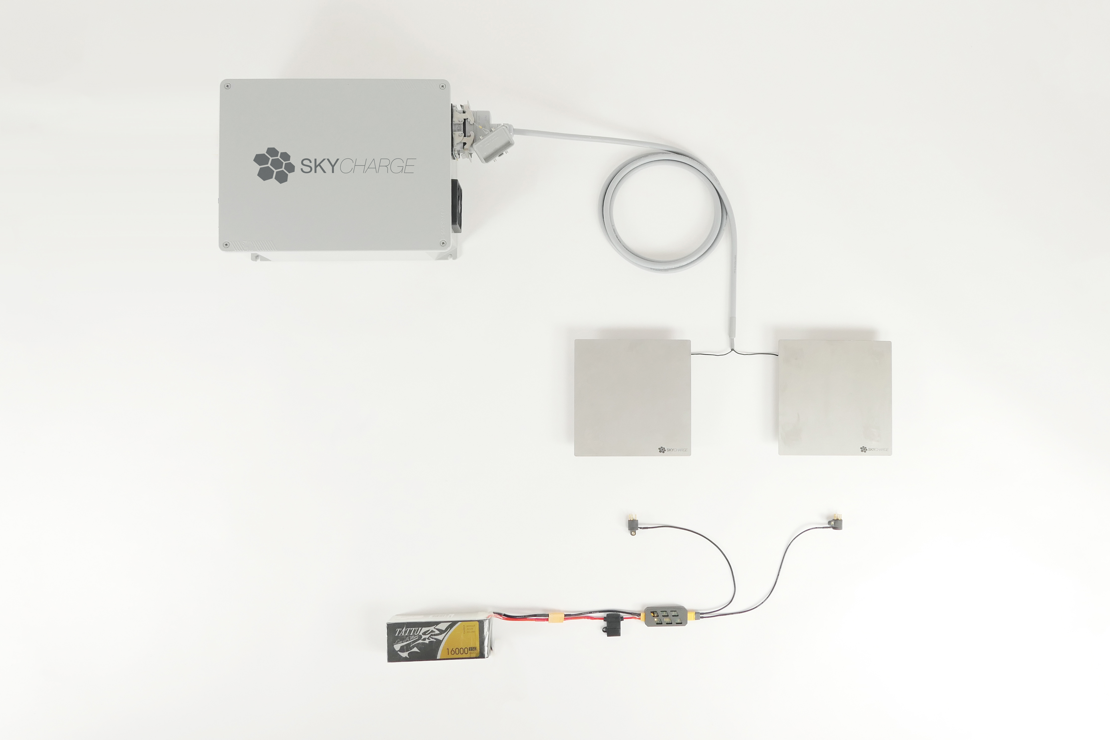
The Skycharge system is an automatic and highly programmable charging system which can be connected to a variety of contact solutions including charging contacts, charging pads, and docking systems. This documentation section describes how to assemble and connect the Skycharge system.
The Skycharge system has two key elements: the charge source and the charge sink. During operations, the charge source transfers power to the charge sink. The charge source is connected to your AC power socket and to a contact solution. The charge sink is connected to a contact unit and to the battery.
System components
- one charge source;
- one multicore cable to connect the charge source to a contact solution;
- one charge sink.
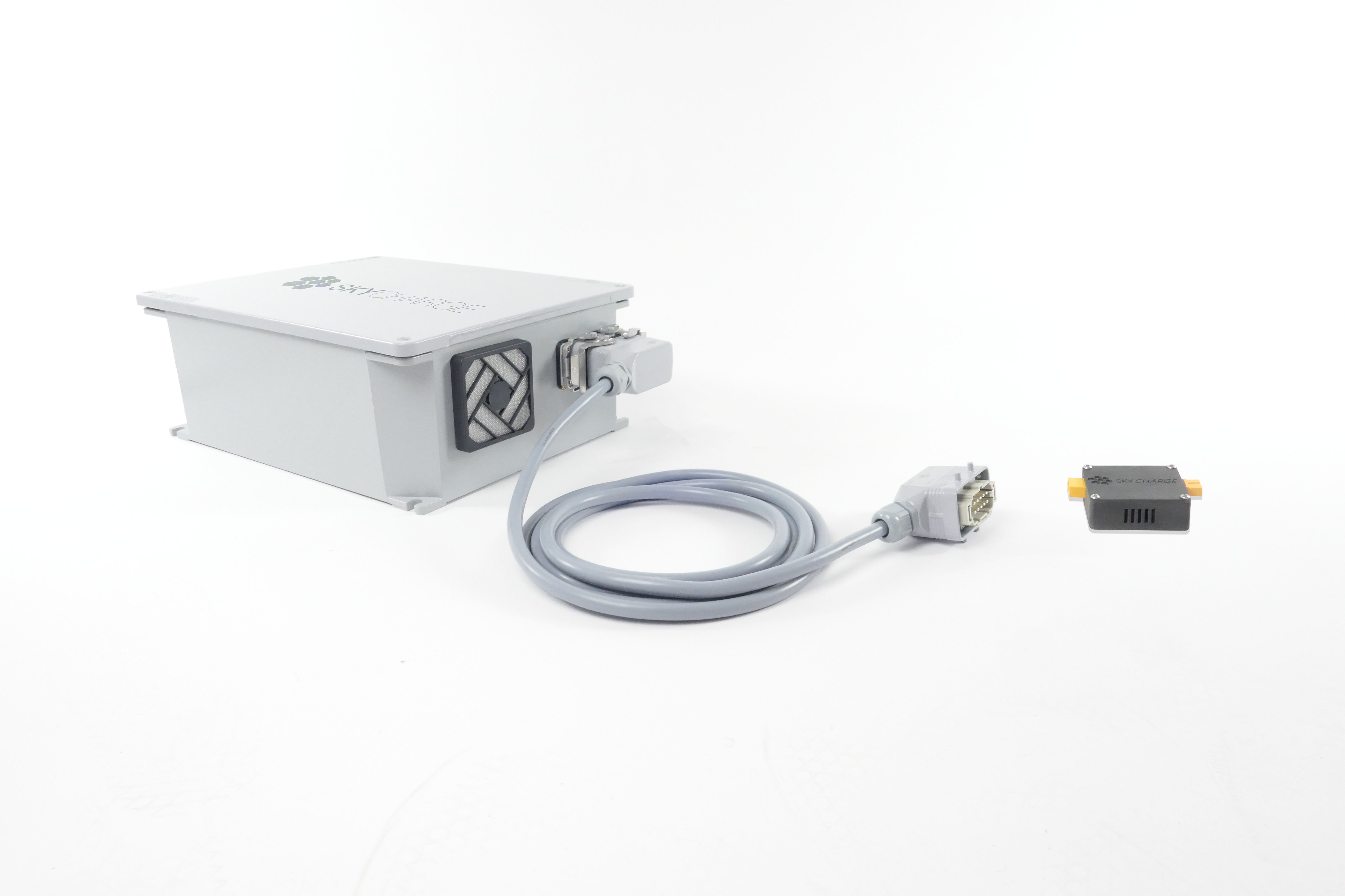
Figure 1 – Skycharge system
Charge source installation
To install the charge source, follow these steps:
- unpack charge source, the charge sink, and the multicore cable;
- connect the charge source AC power cable to your AC power socket; depending on your country, you may need an adaptor or to change the supplied plug.
Charge source front view
On the front side of the charge source are located the sockets for AC power, LAN socket (UTP with RJ45 connector), power switch, AC fuse, and fan breathers.
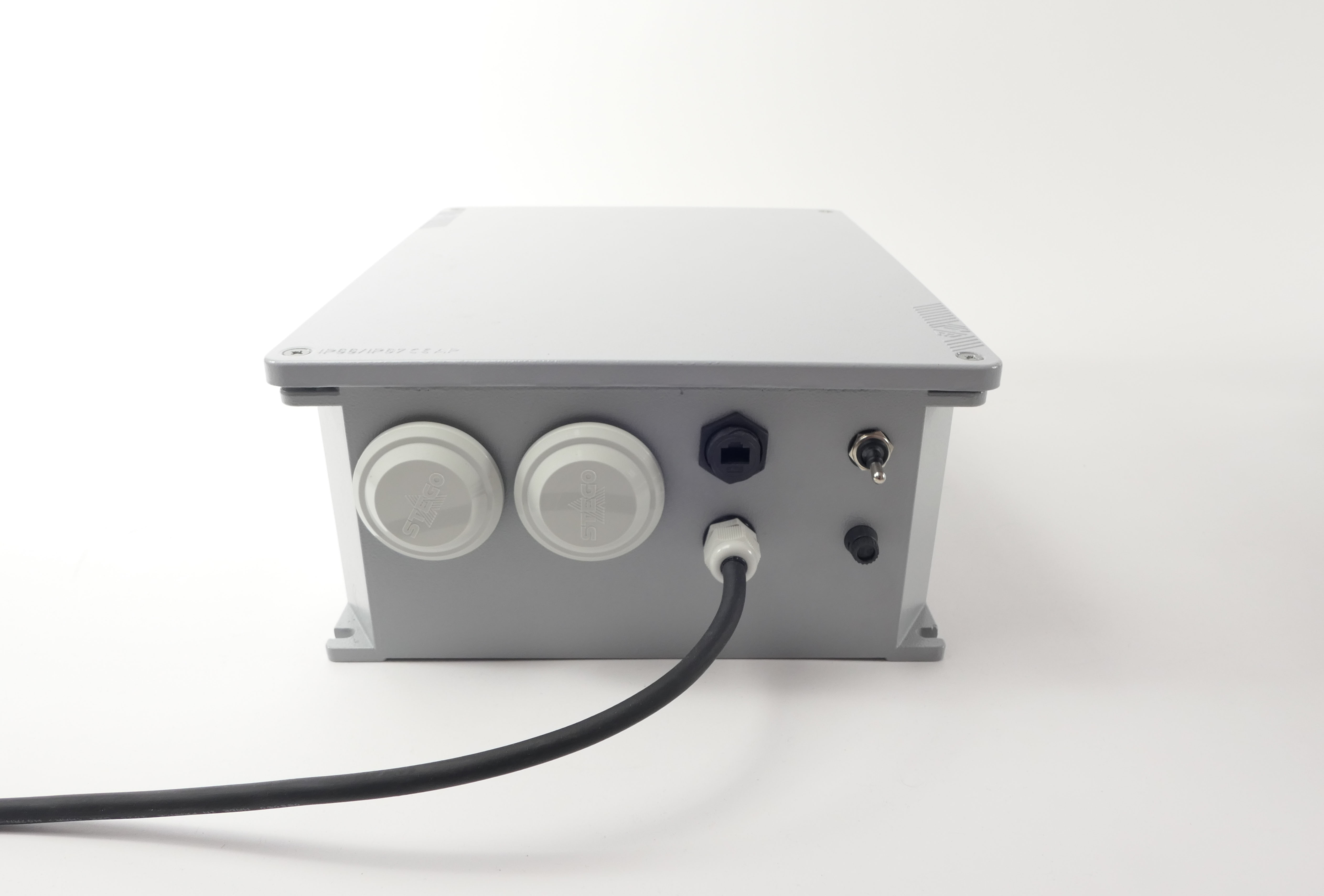
Figure 2 – Charge source box front view
Charge source rear view
On the back side of the charge source is located one input breather and the multicore cable socket.
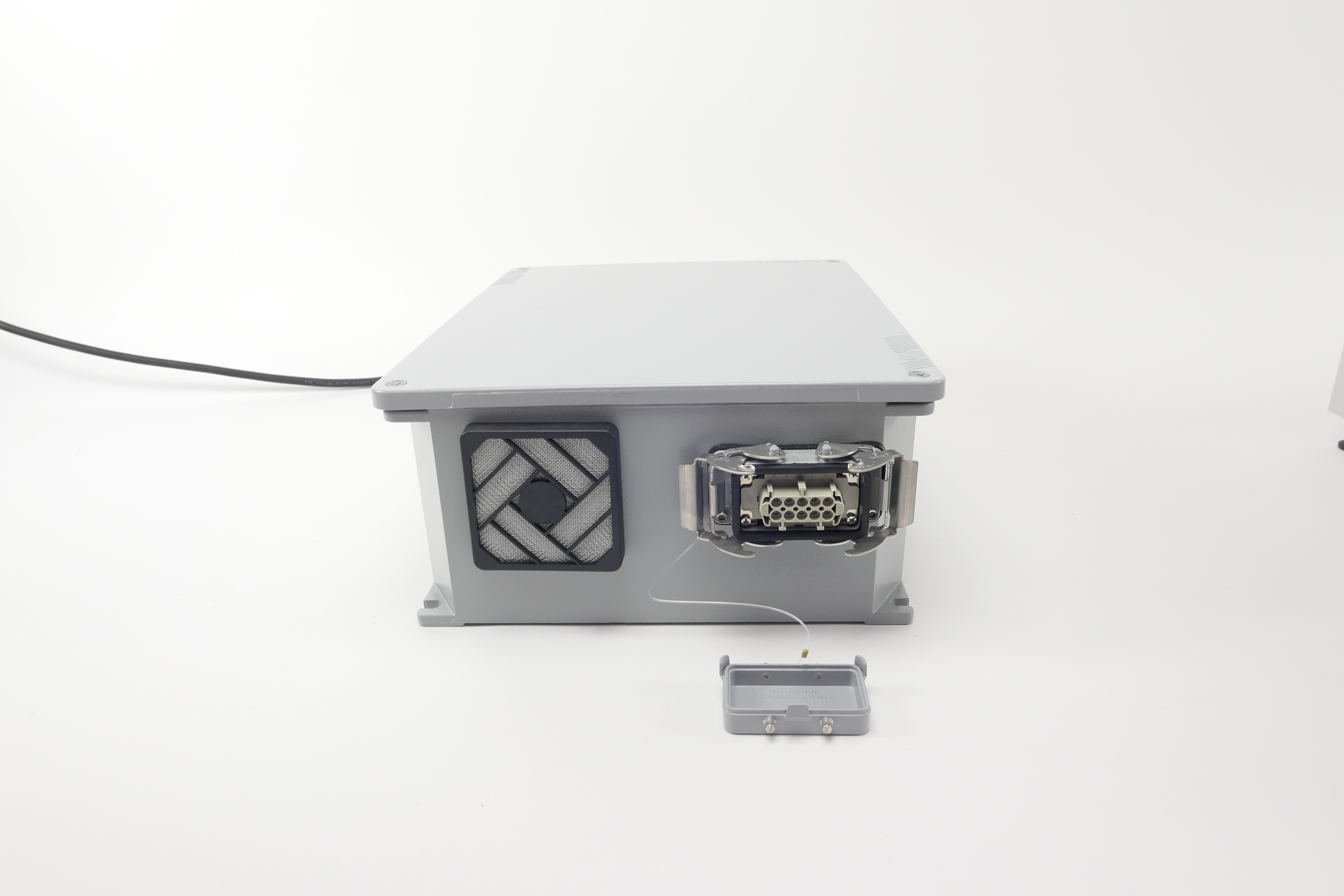
Figure 3 – Charge source rear view
Safe AC connection requiredThe electrical connection to the power outlet must be provided by you connecting the system AC power plug to an electric breaker switch with protection for short circuit and direct contact. The electrical connection must have ground wire connected.
Nine (9) power channelsThe charge source can manage up to nine (9) independent power channels. This powerful feature enables you to build charging platforms of any size and shape, by arranging several charging tiles in a matrix. With this feature, our Bolognini S1 drone charging pad, for example, can charge drones of different sizes, and accommodate inaccurate landings.
Charge sink installation
To install the charge sink follow these steps:
- unpack the charge sink;
- connect the charge sink female XT60 to your contact unit;
- connect the charge sink male XT60 to your battery;
In Figure 4 below, the charge sink is connected to two different contact unit types.
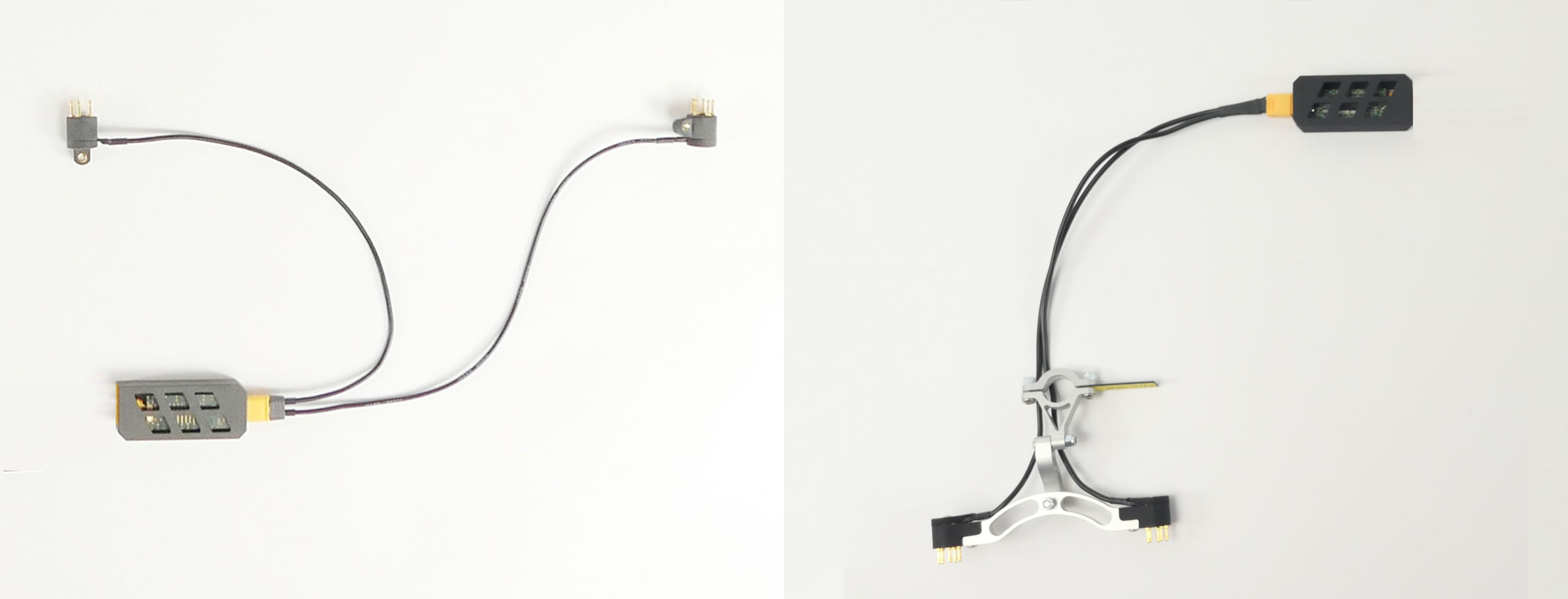
Figure 4 - Charge sink connected to contact units
In Figure 5 below, the charge sink is connected to a battery and to a contact unit.
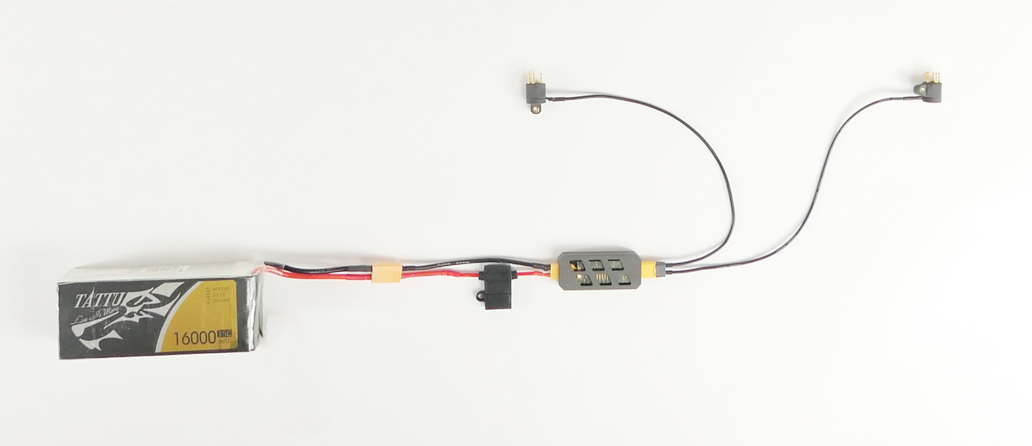
Figure 5 – Charge sink connected to a battery
In Figure 6 below, the charge sink is connected to a battery BMS and to a contact unit. In this case, the BMS is connected to two Li-Po batteries connected in series.
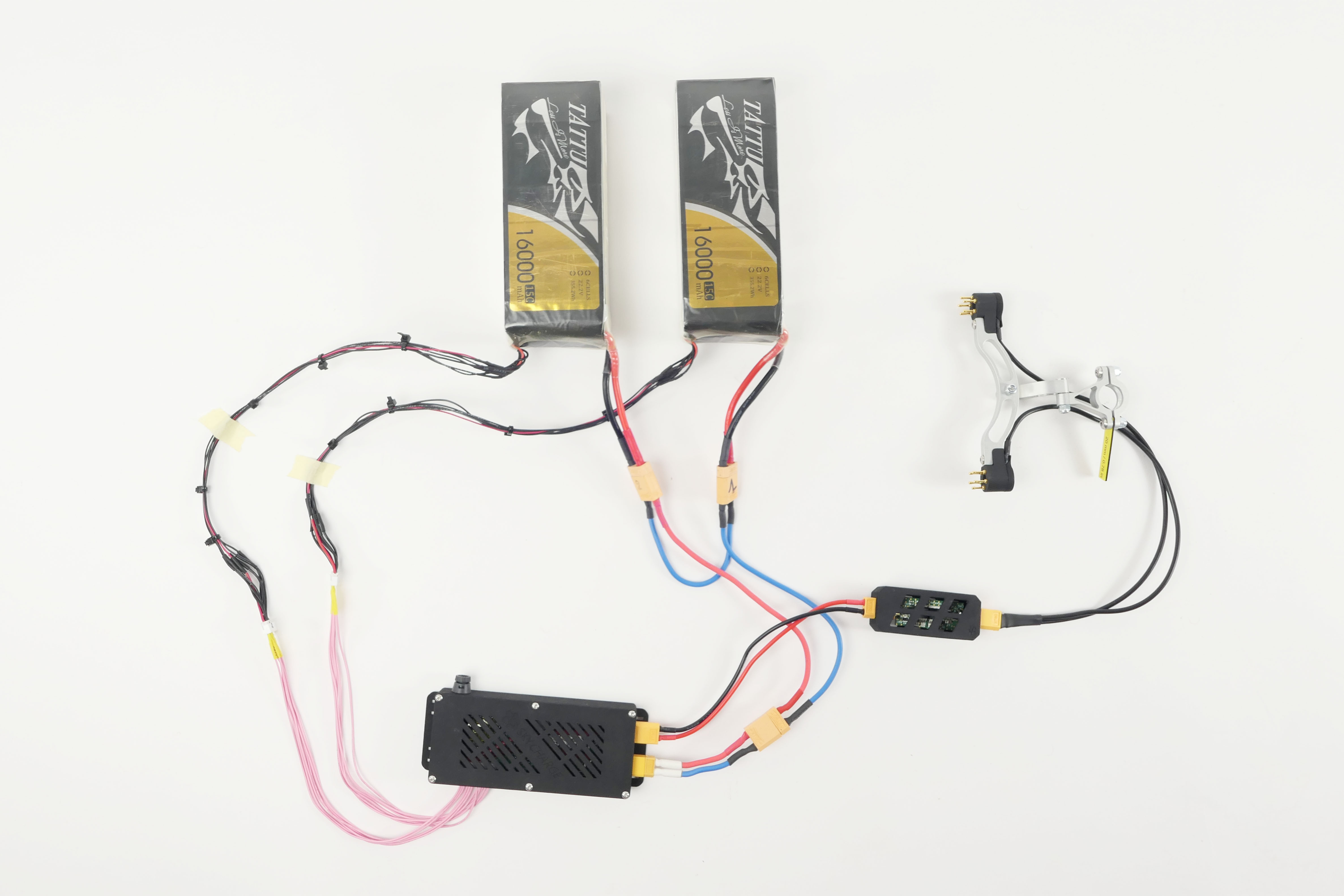
Figure 6 – Charge sink connected to a battery BMS
Integration with BMS/PCMDepending on your battery specification, to repeatedly charge your battery automatically, you may want to integrate a BMS with charge-balance functionality with your battery. In this case, the charge sink is connected to the battery BMS/PCM. Figure 6 above is a good example of this configuration. The DC power flows from the contact unit, through the charge sink, to the BMS that charges the battery and keeps its cells balanced. There are plenty of ready-to-use BMS on the market with charge-balance functionality.
Integration with smart batteriesSmart batteries, included for example in all recent DJI drones, already embed a BMS/PCM circuit with charge-balance functionality. In this case, the charge sink is connected directly to the battery power cables.
Rewire the sink boardIf you need to rewire the sink board connection cables or change the connectors, always respect polarity and do not reverse the charge sink connections’ as in some cases this may cause permanent damage to the charge source.
Updated about 1 year ago
